Week 07 : Computer controlled Machining
the assignment for this week are:
The group assignment
- Test runout, alignment, speeds, feeds, and toolpaths for your machine!
The individual assignment
- Making something BIG, like no matter what it's like , as long as it's B . I . G !!!!!
Group Assignement
Link For the group AssignementIndividual Assignement
For this week's assignment we had to work again with the big version of the CNC Milling Machine that we used previously in the 4th week!
Frankly I was little bit afraid at first like always to mess things up ; this is my first time working with something so big. However things got alot complicated after the outbreak of COVID-19 in the entire world: our country was in such critical situation, 80% of the citizens had to stay in quarantine, everythings had to close because of the fast spread of the virusand the workflow stoped to some degrees
So the access for the Fab-lab was kinda limited, thus I started with doing the designing work and afterward,if possible, we were going to use the CNC.
CNC Milling Machine
WHAT IS A CNC MILLING MACHINE?CNC milling is a certain type of CNC machining. Milling is a process that is quite similar to drilling or cutting, and milling can perform these processes for a variety of production needs. Milling utilizes a cylindrical cutting tool that can rotate in various directions. Unlike traditional drilling, a milling cutter can move along multiple axes. It also has the capability to create a wide array of shapes, slots, holes, and other necessary impressions. Plus, the work piece of a CNC mill can be moved across the milling tool in specific directions. A drill is only able to achieve a single axis motion, which limits its overall production capability.
WHAT IS A CNC MILL AND HOW DOES IT WORK?
IMPORTANT TIPS FOR FIRST-TIME CNC MACHINISTS.
BITS
CNC machines are just like any other machines that need tools to work. And for its routers need bits, and these bits determine the carving type, resolution, and material.So without the right bits, even the perfect CNC won't be going very far.
An end mill, while similar in appearance to a drill bit, is far more versatile. However, in practice the terms “bit”and “end mill” are often used interchangeably.
But how can someone tell the difference between END MILLS and DRILL BITS?
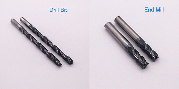
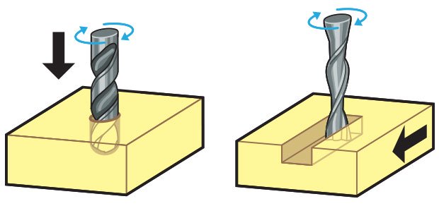
- Drill bits: These drive into the material. They are the best choice for tasks that require material to be removed straight down through the workpiece. They are often used for pre-drilling holes for screws.
- Milling bits (or cutters, carving bits, and end mills): These cut laterally across your material. They are designed to move across the surface of the workpiece, clearing away chips to achieve 3D designs.
Even though bits fall into these two main categories, other variables are always at play, like bit material (solid carbide, HSS, carbide-tipped), flute type (straight, up cut, down cut, compression), number of flutes (1-2 flutes, 2+ flutes), and bit end (fishtail, engraving, V-bit, ball nose).
.jpg)
Tip Shapes and Applications
Each end mill tip shape is designed for a particular purpose. Some common cutter shapes are ballnose, fish tail, surface planing, v-carving, and straight.
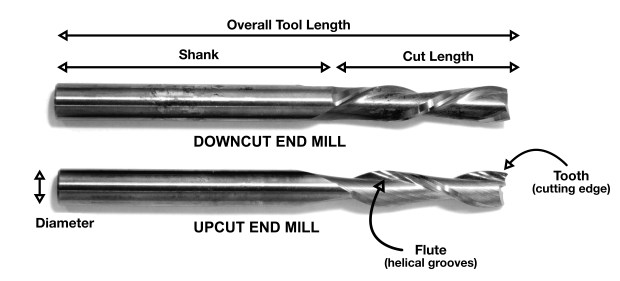
Flute: are the helical grooves that wrap around the sides of the end mill. Each flute has a single tooth with a sharp cutting edge (although there can be more than one) that runs along the edge of the flute.
Chip load: Chipload is the thickness of a machined chip as cut by a specific tool type. More flutes create a smoother surface finish, while fewer flutes remove material fastest, but make rougher cuts.
Proper chipload is important because chips dissipate heat. Hot cutters can lead to suboptimal results, including burned wood, a poor edge finish and dull tooling.
Feed rate: How fast a bit can move laterally through the material, or vice versa. It’s measured in IPM or feet per minute. Therefore, if your chips are unnecessarily large, reduce the feed rate or you may end up ruining the bit.
Speed rate:The speed of the spindle. It’s represented in revolutions per minute (RPM).
Toolpath: This is a coded route that the CNC machine follows to cut. Think of it as a guide for the device.
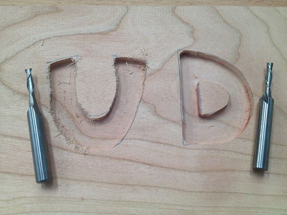
Upcut vs Downcut
Spiral bits are great all-purpose tools that can be used in several applications, but you need to determine the cut direction, which will be informed by the type of material or other variables.
YOU CAN ALSO CHECK THIS FOR MORE INFOS:
Guide to cnc router bits all you need to know
There's some factors you should take in consideration in selecting your TOOL before starting MILLING
WHAT ARE THOSE FACTORS ?
Bit manufacturers go to great lengths when engineering their cutters, but selecting the right bit still requires some due diligence. There are plenty of variables to take into account when picking the right bit, but the type of project and material are two factors that you must always take into consideration.
PROJECT SUITABILITY:What project are you undertaking?
For instance, detailed work like lettering requires a V-bit (sometimes called engraving bits, V-groove bits, or V-carving bits). As the name suggests, V-bits have a cutting profile in the shape of a ‘V’. They come with different “included angles”, and this will determine what they’re used for. A 60° V-bit, for example, will give you smaller details compared to a 90° bit, which is well suited for larger or shallower details or letters.
MATERIAL COMPATIBILITY:What are you cutting? Is it hard or soft wood? Is it stainless steel, fiberglass, MDF, acrylic, or aluminum?
The material matters. It matters so much that you will find different grades of carbides used for different materials. Going for the wrong bit could be detrimental to the bit or even the machine. Plastic will require a specific bit (specifically one that will not melt it) and so will aluminum and plywood.
Selecting the right tool for the job is just as important as choosing the right equipment in the first place.
You can also check:
5 factors should consider selecting cnc tooling ENDMILLS Guide to cnc router bits-Designing
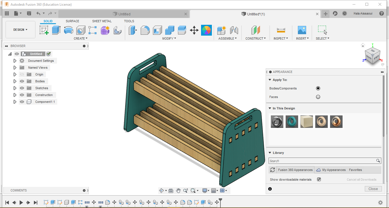
Like any previous Assignment, we start designing using CAD programs and as usually I'm using FUSION 360 for this part.
I decided to do a flat pack shoe rack that I need to pack my shoes after moving into a new appartement
.png)
I started with "personalizing" the parameters of my design, since I had no idea about the mesurement of the Machine, nor the tools disponibility (that I'm going to use) after the total shutdown of many things here in TUNISIA.
.gif)
As the always start, we had to make the first sketching of the Model; I started doing one of the faces.
then, I made the first hole(in which the racks is going to be stuck)
And after doing the extrude thing I started sketching one of the racks
.png)
I made he measurement of the hole is going to be the reference of what I'm
.png)
.png)
And now I needed to do the holes for these racks.
.png)
And since I was thinking about doing two rows of racks: so I needed to make holes for them.
.gif)
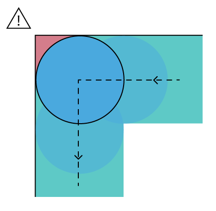
And now , since I'm going to use CNC afterwards, so most of holes need to be in the shape of DOGBONES.
But why Dogbones?
You should keep in mind that with a rounded bit you won't reach all the way into n inside angle; it's so easy to get tripped up by the physical size of the bit when making designs.
Problem fixed?!
If you're using Fusion, all what you have to do is dowloding the Dogbone plugin from here and follow the instructions on internet to add it in Fusion.All what you need to do afterwards is selecting the norrow corners and transform them to the shape of dogbones automatically:
.png)
.png)
Even these corners:
.png)
.png)
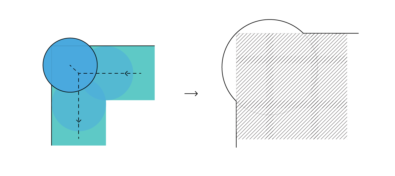
Another alternative?!
The T-bone
There is another way to cover that red area, though. Instead of 'pushing' a circle into the corner of your design, you can push a circle directly in one direction, up or sideways.
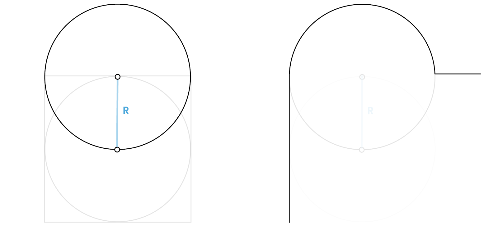
Source: learn about milling inside corner
Anyways,
I wanted to make every edge as roundy as possible
.png)
.png)
And now it's time for sticking everthing together:
.gif)
What I used:
MOVE/COPY option
.png)
Plus; I made some 'holders' into these faces!
.png)
Done!!
.gif)
For this part, I ended the whole model with making the other face!
Final touch:
Time for some DRILLS
Design using the Fusion
However, first of all I had to lay my parts out flat using a fusion add-in called NESTER and here things can get lil' bit tricky
Here's some steps on how to add it to FUSION:
Download it
.png)
EXTRACT THE FILE
.png)
TOOLS>ADD-INS>Scripts and Add-Ins
.png)
Click on the (+) to open the scripts location
.png)
copy the scripts from the file you already downloaded and then paste it into the file adress you opened from the previous step
.png)
PASTE it here
.png)
Then, close FUSION for the new add-in to run perfectly
PS: for the program to run , all of your pieces has to be component "a lesson to learn"
Then you click on the faces of your components to lay them on the piece of wood you already prepared with your desired measurements
.png)
and we end it with putting the drill settings; Manufacture>setup
.png)
.png)
.png)
.png)
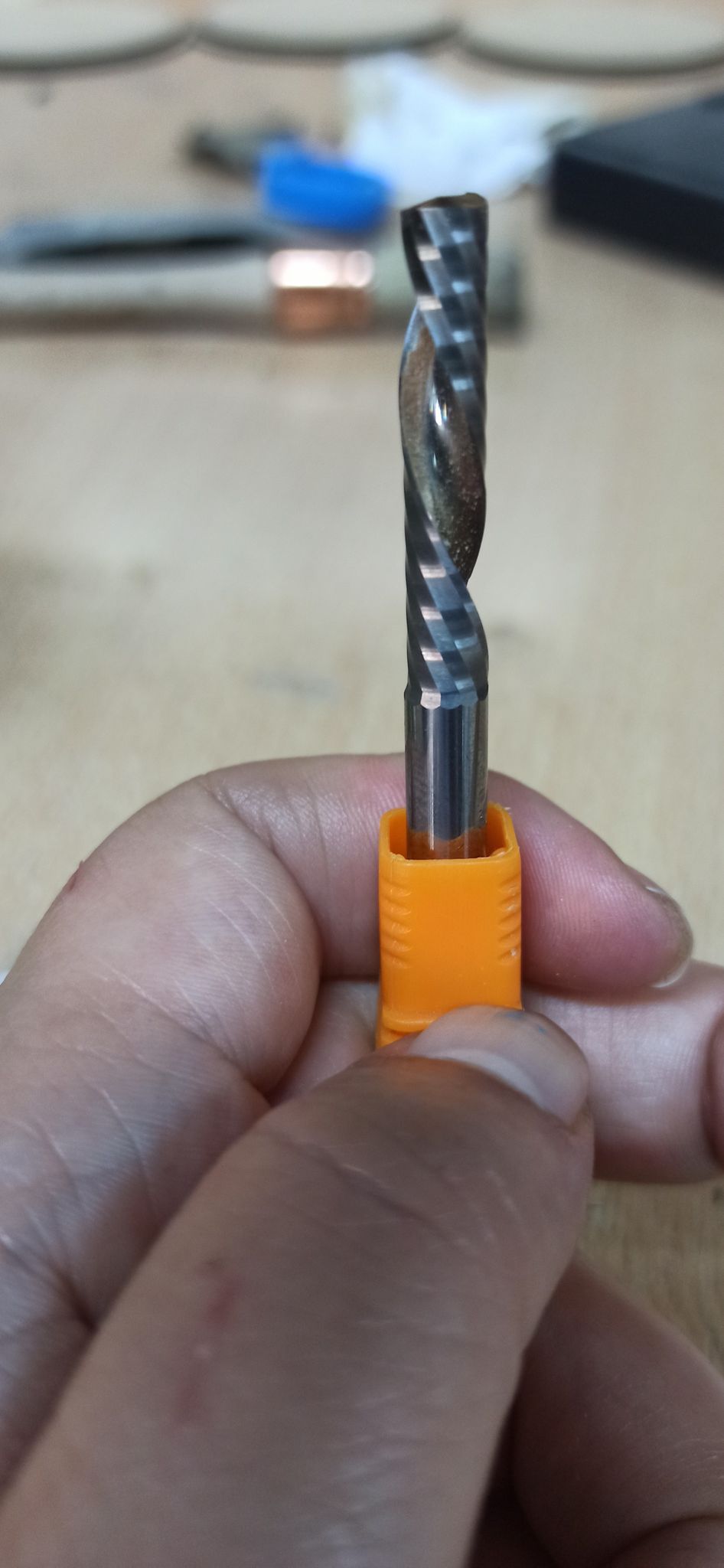
Then the sitting of the endmill that we used for the drill!
.png)
.png)
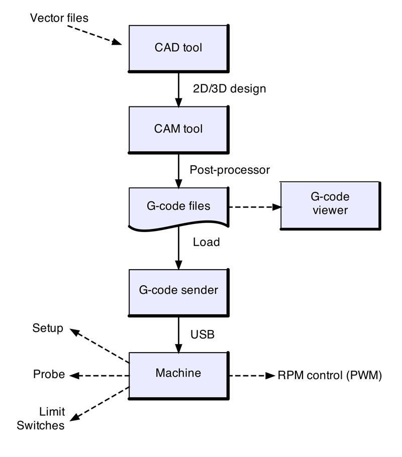
Workflow with the CNC machine
So after defining the toolpath and everything, I extracted the Gcode: ACTION > Post process.
%20-%20Copy.png)
Then we had to copy the saved file into USB and transfer it to the CNC machine that we're going to use
.jpeg)
after putting our bit in the coulet of the cnc
Now we had to start working after making sure that we strapped in our MDF Board using clippers and placing the machine in its 0 position.
.jpeg)
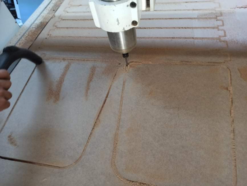
and let do it's work!
.jpeg)
.jpeg)
.jpeg)
.jpeg)
For the excessive dust from the MDF board, we had to use the vacuum to clean it.
So after completing the whole procedure, it was the time to assemble all of the parts, but before thats ( though, the board was too heavy to be carried only by one person ) we had to take out all of the parts there
.jpeg)
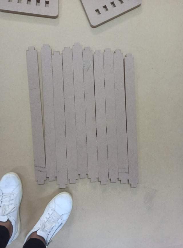
.jpeg)
Then assemble it together !!!
.jpg)
.jpg)
.jpg)
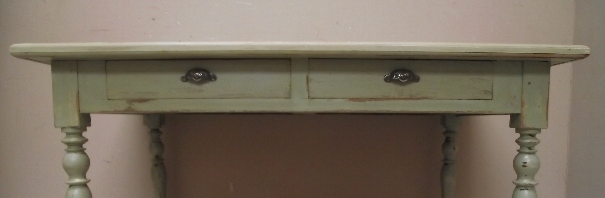
And yes I found a place where to put my shoes on !!!
.jpg)
Generally speaking, we can say that the whole procedure is summarized in this